Sunday, January 26, 2014
Panel Raising Plane


Other than the main blade, it was equipped with an auxiliary iron for moulding the inner edge of the panel and a nicker for scoring the wood across the grain.
Woods are lamellar beech, wengè and cherry (handle). Here is the result:


The main blade (25° skew angle) has a chipbreaker and the "Stella Bianca" mark. It is a new old stock blade and showed very good quality and ability of keeping a sharp edge. The moulding iron comes from a file, shaped by bench grinder.
The first nicker (red point) comes from an old plane iron; it is inserted in a mortice and held in place by a wedge. Another nicker (green point) is present; it avoids the tearout of the moulding edge when the plane cuts across the grain.


The main wedge is kept in place by a 5 mm steel rod I obtained from a screwdriver.


A description of building the plane follows.
 This is a Krenov-style plane, assembled in three parts, one central part where the main cutting group is held and two lateral parts.The central part will be large enough for the blade bedded in a skewed position.
 In this case it was obtained by gluing two pieces together (final width ca. 50 mm). The two lateral pieces are ca. 15 mm thick. The plane length is 13" (keep stock pieces some inches longer).
I glued a wengè sole (ca. 10 mm thick) to the three body pieces.
I glued a wengè sole (ca. 10 mm thick) to the three body pieces.
Then the left side has been screwed to the central part (temporarily) and a 6° angle (typical sole angle for these planes) cut by bench saw.
 The left side is removed and a dozuki saw is used for cutting the bed and the facing part
 The bed angle is 50° (25° skew).

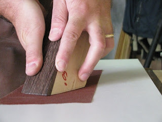
Try to cut as more precisely as possible; dont worry if the cut is approximative. The successive step of lapping the bed on abrasive paper (150 grit) will true it and dont matter if the final angle will be a couple of degrees more or less: more important is that the blade will seat firmly on its bed.

Cut the slot for cap iron screw and mould the right side sole by routering it (roman ogee profile).

The main nicker groove has a sloped bed, so its tip is aligned with the rebate inner wall.

On the right side, in the same position, cut a groove with parallel bed. The two grooves will form the slot for the nicker and its wedge.
 The four plane parts (two central and two lateral) are coupled by screws: the left part sole will be flush with the central part, while the right one will be slightly higher (3 mm) so the main rebate will be created.
The two central pieces are distant enough for permitting to the cutting edge just to pass trough the mouth.
Now we can insert the pin, (I needed a longer drill bit), paying attention the boring slope corresponds to seat.
Shape the wedge so it could firmly keep the iron in place.
Shape the wedge so it could firmly keep the iron in place.

A good wedge should can work simply inserted by hand.
The pin is cut a couple of mm shorter than necessary.
Now is the moment of gluing sides to two central pieces.
The pin is cut a couple of mm shorter than necessary.
Now is the moment of gluing sides to two central pieces.


A Forstner bit will help us to create the chip escapement. The bed is 5-6° inclined to right, so the shaves can escape more easily.

Glue up a 3 cm wide strip on the right side. It forms the moulding blade slot.
I decided to re-mouth the plane for inserting an end-grained piece before the mouth. It should offer a bigger resistance to wear.
I decided to re-mouth the plane for inserting an end-grained piece before the mouth. It should offer a bigger resistance to wear.

We are ready to level the sole. Do it with irons inserted in place, by 80 and 150 grit abrasive paper glued to a flat surface.

Sharp the blades so they could follow the wood profiles.
The second nicker cleans the inner edge of panel moulding. It comes from a Stanley 78 spare part (you can order here also).

In order to positioning it to right level, where the moulding curve ends, I bored with two drill bits, 25 and 11 mm.
The posterior plane part is tapered and holds the cherry handle.


A slide dovetail joint insures it to plane body. the male joint part has been cut by a dedicate plane.
The lateral fence and depth stop are screwed to body and have slotted holes for regulating field width and depth.

A strike button and a cherry insert (it covers the pin hole) on the left side complete the plane.
It received three coats of shellac and two coats of wax.

The following short video shows the plane in action.
What a satisfaction!
Subscribe to:
Post Comments (Atom)

No comments:
Post a Comment