Sunday, January 26, 2014
Drawing a Greene Greene Cloud Lift with a CAD Program
Since I work many styles besides Greene and Greene I sometimes have to fool around for a minute til I remember how exactly to do this when I have to do it. Im putting it here for myself and anybody else who wants it ... Enjoy ! Click to enlarge ...

Read More..

Panel Raising Plane
Since several years I wished to make a panel raising plane. Inspiration came to me from a model listed in the 1934 UMAT catalogue.

Other than the main blade, it was equipped with an auxiliary iron for moulding the inner edge of the panel and a nicker for scoring the wood across the grain.
Woods are lamellar beech, wengè and cherry (handle). Here is the result:


 The plane (13" long, blade bedded at 50°) has a razee shape like motif and is provided with an adjustable parallel fence as well as a depth stop. The fence permits changing of rebate width.
The main blade (25° skew angle) has a chipbreaker and the "Stella Bianca" mark. It is a new old stock blade and showed very good quality and ability of keeping a sharp edge. The moulding iron comes from a file, shaped by bench grinder.
The first nicker (red point) comes from an old plane iron; it is inserted in a mortice and held in place by a wedge. Another nicker (green point) is present; it avoids the tearout of the moulding edge when the plane cuts across the grain.


The main wedge is kept in place by a 5 mm steel rod I obtained from a screwdriver.
 The cherry handle is glued to the plane body by a sliding dovetail joint (PR means Panel Raising and 13 is the plane length).

A description of building the plane follows.
 This is a Krenov-style plane, assembled in three parts, one central part where the main cutting group is held and two lateral parts.The central part will be large enough for the blade bedded in a skewed position.
 The left side is removed and a dozuki saw is used for cutting the bed and the facing part
The bed angle is 50° (25° skew).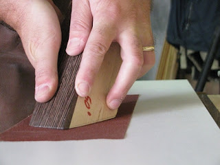


On the right side, in the same position, cut a groove with parallel bed. The two grooves will form the slot for the nicker and its wedge.
 The four plane parts (two central and two lateral) are coupled by screws: the left part sole will be flush with the central part, while the right one will be slightly higher (3 mm) so the main rebate will be created.

The two central pieces are distant enough for permitting to the cutting edge just to pass trough the mouth.


 Cut the slot for the moulding plane by sawing and chiselling it, then clean by a router plane.
A Forstner bit will help us to create the chip escapement. The bed is 5-6° inclined to right, so the shaves can escape more easily.


We are ready to level the sole. Do it with irons inserted in place, by 80 and 150 grit abrasive paper glued to a flat surface.

In order to positioning it to right level, where the moulding curve ends, I bored with two drill bits, 25 and 11 mm.
The posterior plane part is tapered and holds the cherry handle.


The following short video shows the plane in action.
What a satisfaction!
Read More..
Other than the main blade, it was equipped with an auxiliary iron for moulding the inner edge of the panel and a nicker for scoring the wood across the grain.
Woods are lamellar beech, wengè and cherry (handle). Here is the result:
The main blade (25° skew angle) has a chipbreaker and the "Stella Bianca" mark. It is a new old stock blade and showed very good quality and ability of keeping a sharp edge. The moulding iron comes from a file, shaped by bench grinder.
The first nicker (red point) comes from an old plane iron; it is inserted in a mortice and held in place by a wedge. Another nicker (green point) is present; it avoids the tearout of the moulding edge when the plane cuts across the grain.
The main wedge is kept in place by a 5 mm steel rod I obtained from a screwdriver.
A description of building the plane follows.
This is a Krenov-style plane, assembled in three parts, one central part where the main cutting group is held and two lateral parts.The central part will be large enough for the blade bedded in a skewed position. In this case it was obtained by gluing two pieces together (final width ca. 50 mm). The two lateral pieces are ca. 15 mm thick. The plane length is 13" (keep stock pieces some inches longer).
I glued a wengè sole (ca. 10 mm thick) to the three body pieces.
I glued a wengè sole (ca. 10 mm thick) to the three body pieces.
Then the left side has been screwed to the central part (temporarily) and a 6° angle (typical sole angle for these planes) cut by bench saw.
The left side is removed and a dozuki saw is used for cutting the bed and the facing part The bed angle is 50° (25° skew).
Try to cut as more precisely as possible; dont worry if the cut is approximative. The successive step of lapping the bed on abrasive paper (150 grit) will true it and dont matter if the final angle will be a couple of degrees more or less: more important is that the blade will seat firmly on its bed.
Cut the slot for cap iron screw and mould the right side sole by routering it (roman ogee profile).
The main nicker groove has a sloped bed, so its tip is aligned with the rebate inner wall.
On the right side, in the same position, cut a groove with parallel bed. The two grooves will form the slot for the nicker and its wedge.
The four plane parts (two central and two lateral) are coupled by screws: the left part sole will be flush with the central part, while the right one will be slightly higher (3 mm) so the main rebate will be created. The two central pieces are distant enough for permitting to the cutting edge just to pass trough the mouth.
Now we can insert the pin, (I needed a longer drill bit), paying attention the boring slope corresponds to seat.
Shape the wedge so it could firmly keep the iron in place.
Shape the wedge so it could firmly keep the iron in place.
A good wedge should can work simply inserted by hand.
The pin is cut a couple of mm shorter than necessary.
Now is the moment of gluing sides to two central pieces.
The pin is cut a couple of mm shorter than necessary.
Now is the moment of gluing sides to two central pieces.
A Forstner bit will help us to create the chip escapement. The bed is 5-6° inclined to right, so the shaves can escape more easily.
Glue up a 3 cm wide strip on the right side. It forms the moulding blade slot.
I decided to re-mouth the plane for inserting an end-grained piece before the mouth. It should offer a bigger resistance to wear.
I decided to re-mouth the plane for inserting an end-grained piece before the mouth. It should offer a bigger resistance to wear.
We are ready to level the sole. Do it with irons inserted in place, by 80 and 150 grit abrasive paper glued to a flat surface.
Sharp the blades so they could follow the wood profiles.
The second nicker cleans the inner edge of panel moulding. It comes from a Stanley 78 spare part (you can order here also).
In order to positioning it to right level, where the moulding curve ends, I bored with two drill bits, 25 and 11 mm.
The posterior plane part is tapered and holds the cherry handle.
A slide dovetail joint insures it to plane body. the male joint part has been cut by a dedicate plane.
The lateral fence and depth stop are screwed to body and have slotted holes for regulating field width and depth.
A strike button and a cherry insert (it covers the pin hole) on the left side complete the plane.
It received three coats of shellac and two coats of wax.The following short video shows the plane in action.
What a satisfaction!
Birch Windfall
Well okay, not an actual windfall (as it was cut to avoid that) but a windfall of wood nonetheless. Our Alaskan birches dont tend to get very large, at least around here, because they either blow down or get crowded out by the spruce. This big guy was too close to the house of some friends and was making them nervous - which is why I found it on their lawn.
A call to my brother Josh, (who took the smaller stuff for his wood stove) and here was my haul:

My idea was to air dry it (I love the way air dried wood works with hand tools) and use it for all sorts of projects. The challenge is to avoid checking (splits) as the wood dries. If the wood is dried in the round, it will almost certainly check, as the wood shrinks tangentially to the grain much more than radially. In other words, as the outer rings of grain try to shrink into smaller rings, they cant move inwards enough to allow them to stay whole, so they split apart. The easiest way to do this is to split the wood into halves or wedges, which allows the wood to move freely as it dries and shrinks (the angle of the wedges become more acute as they dry).
Heres a photo essay of the splitting process.
Step 1: Start a split with the axe.

Step 2: Use a sledgehammer and a sharp wedge to open the split farther. I scored this old logging wedge down in Oregon and it is perfect for this step.

Step 3: Open the split wider with a larger wedge.

Step 4: Leapfrog the sharper wedge and advance the split again.

Step 5: Add another large wedge. A lot of the time I can leapfrog the large wedge to the new position, but this log was not in the mood to cooperate. The grain from the large branch (cut flush) complicated things and the first large wedge didnt release.

Step 6: Split complete.

Alternate Step A: Make a glut. I think traditionally these are made from some tough wood like dogwood. But seeing as I was at least a couple thousand miles away from the nearest dogwood, but only about ten feet from a scrap lumber pile, I made mine from an old 2x4.

Alternate Step B: Use the glut like a huge wedge (which of course is exactly what it is :) to split logs that are particularly large and/or ornery.

And here is the final result after a few hours of work.

And the tool kit:

I dont have any particular projects in mind for this wood, but Im sure something will come to me.
Saturday, January 25, 2014
Hold This For Me Will Ya
I have been messing about with wood on temporary benches for who knows how long now. I have used everything from a few planks spread across a couple of old oil drums to working off of one of those silly "Workmate" things. Since moving out of the condo and into a house a year-and-a-half ago, things have slowly gotten better. My tool cabinet is still with me and continues to sit in my office. It has a nice little worktop that is just the cats behind when it comes to height and I dont have to travel far to get my hands on the tool I need. This spring, I built a large, heavy bench out of pressure-treated lumber that sits outside on our backyard patio. It is great for doing the slug-work like facing boards and ripping planks, but it does require schlepping the tools I need back and forth. I wouldnt trade that piece of shit for the best Schwarz-built bench he has to offer, though, because that would mean I would have to work inside and that, Im afraid, aint for me. For me, this is the perfect set-up. When the weather is nice, Im out working in the open air and when it isnt, Im tucked away in my office working on bits and pieces and messin with things that dont produce much dust or need much room.
I have learned one major lesson while building these fussy, little mounts, though - I need a damned vise. Yesterday I was trying to flatten the face of a piece for the No.10½ plane mount. The stock was about 12" long, 2½" wide, which I can handle with a bit a fussing. What drove me to drink, though, was its thickness. Being ³⁄₈" thick on one side and 1" on the other called for some serious gymnastics to not only get it held down, but held down in such a way as to allow the plane to travel the full length of the stock without hitting anything. What a royal pain in the butt. I got it done, but afterwards I realized that I hadnt enjoyed it one bit, and if Im not enjoying it, why the hell am I doing it?
Faced with the reality that I needed a vise, I had to figure out what to do about it. Both worktops call for a removable style of vise. There is no sense mounting one permanently on the bench outside as the rain and snow would destroy it in a season and mounting one on the tool cabinet would severely limit its use, not to mention killing a good portion of my work area. If I did go with a removable style, the only type I know of are the metal cast variety, which Im not fond of from an aesthetic standpoint. I also know the edges of my planes and chisels wouldnt be to happy about working around one either, given what a klutz I am.
What I decided I needed was a small, portable vise made of wood with its main function being facing boards, especially the smaller, oddly-shaped ones that I seem to be involved with so much lately.
This is what I came up with...

Once I had an idea of what I wanted and how it had to be built, I took a look at the tools I already have. I have a set of old thread cutters, the largest of which is 1", so the single, centre screw is 1" in diameter. My little lathe holds a maximum of 15" stock, so the screw in its entirety, is 14½" long. Because it cant add too much height to the benches it will be attached to, I decided to limit it to 2¾" high. To keep the face square, I added two ¾" maple dowels on either side to help keep it aligned. I settled on an overall size of 25½" by 12" and included two rows of dog holes which should allow it to hold all the weird and wild-shaped pieces of stock I have been coming up with at late. The big question is, what is the easiest way to attach it to the bench? At this point, I plan to just add a couple of cut-outs on either side to accept the heads of regular clamps, but Ill have a look around this weekend to see if there is something less cumbersome about. I have ordered the stock in beech and should be picking it up within a week or two. Ill keep you posted how I make out with it.
In truth, Im looking forward to getting at it and finally working wood without the added frustrations of not having anything to hold it.
As usual, if anyone has an idea they would like to share with me about this, Id be truly grateful.
Peace,
Mitchell
Sylvania Ohio built in Beginnings
Ive begun construction on the built-in in Sylvania, Ohio! The week prior to this point has been filled with prep work for this project. Ive spent the previous week buying, sanding, priming, and painting the materials to be used here.
The first picture is the drawing showing the general layout of the built-in, and what the desired features are going to be. The more time spent on this phase with the owners the better. Its where ideas, wants, and needs get all hashed out, and it also eliminates surprises. The drawing shows wider and deeper bench areas below the windows, decorative areas on either side of the windows, a large overhead display area, a center open area to accommodate the tv (to include a pull out shelf), and a lower center section to house the electronics.


Read More..
The first picture is the drawing showing the general layout of the built-in, and what the desired features are going to be. The more time spent on this phase with the owners the better. Its where ideas, wants, and needs get all hashed out, and it also eliminates surprises. The drawing shows wider and deeper bench areas below the windows, decorative areas on either side of the windows, a large overhead display area, a center open area to accommodate the tv (to include a pull out shelf), and a lower center section to house the electronics.
Here is a picture of our "blank canvas", and the area to be worked in. There are two floor registers to deal with. I will be installing ductwork to project them out of the front of the window seat sections.
Over the last day and a half, I have built the two window seat sections. I initially built a subframe out of 2x3 material, and trimmed and capped it with my painted 1x4s. Ive installed the seat tops, which I made out of beefier 5/4 stair treads to give it a bolder look. Ive also routed the ductwork to the front of the seat sections, and dropped in 1/4 piece to cover the ducts and give some storage space.
I will be making doors for the front of these sections to finish them off.
Ghetto WorkCenter Boom Arm Part II The Video
Earlier in the week, I began my series on my Ghetto WorkCenter Boom Arm. Its my homemade version of a boom arm and platform that fits on the systainers that fit on my vacuum.
I was hoping to finish the description about the Ghetto WorkCenter Boom Arm before I posted the video, but Im down with a cold, so heres the video (its an easy post to write). Ill get back to the construction in my Monday post.
Read More..
I was hoping to finish the description about the Ghetto WorkCenter Boom Arm before I posted the video, but Im down with a cold, so heres the video (its an easy post to write). Ill get back to the construction in my Monday post.
Do you have a boom or hook to keep your vacuum hose out of the way?
My Old Toolbox
Ive rediscovered my old toolbox. I made this tote in an Industrial Arts class my freshman year of high school, which I believe makes this the oldest woodworking project of mine that still exists. I have no memory of actually using it.
Somehow this thing followed me up to Alaska (I dont even remember packing it), spent some time in my brothers shed, and more recently moved into a funky corner of my garage (on the fringe of my shop space), where it promptly got buried under layers of junk.
A few weeks ago, my brother Josh was out in my neck of the woods harvesting spruce poles for a sod house he will be building on his remote property. I was heading out to help, but needed some good way of taking a small kit of tools along (axe, hatchet etc.) What I needed was a large tool tote...
Hey! What about that one buried over there? I quickly dug it out (finding the hardware for the never completed treadle lathe and a perfectly usable brace in the process - how many of these do I have?)and cleaned it off.
It is very simply constructed - nailed butt joints - but apparently I was very proud of it, because it has my name handwritten in pencil all over it. It was fun to see that - back when I went by "Danny".
I loaded it up and off we went. Here it is in the field:

It easily held my axe, hatchet, disassembled bowsaw, file, sharpening stone, drawknife, hammer and punch (for bowsaw pins), gloves and some snacks.
You could tell it was happy finally getting to do yeomans work after almost 30 years of sitting around!
*** The Candle Till is finished, but the post isnt. That should be coming up next...
Subscribe to:
Posts (Atom)