Showing posts with label plane. Show all posts
Showing posts with label plane. Show all posts
Wednesday, March 5, 2014
Another plane collection
Cosmin sent over pictures of his favorite tool collection: planes. He writes:


Read More..
They have not been inherited as I come from a long line of geeks; all I got was a stack of computer punch cards. I have gathered the planes over less than 2 years, which is just about as long as I have been interested in woodworking. I took some photos of the warzone to give some perspective. Then I placed the planes on item #1 from my honey-do list (11/4 thick walnut bench) and took somes shots. For reference, the walnut piece is exactly 12" wide. I promise I did tidy up the place before I took the shots and I chose the best available angle.
My current interest is building stave shell drums. I am slowly getting there. In the mean time, I am developing a huge interest in hand tools. Next on my list is a Roubo workbench, braces, more drawknives, a beam drill, and a few more drawbore pins.
One car garage shop from several angles
***
ECE planes I acquired from a local retired piano builder, and a Knaus plane
***
Vintage violin maker planes
***
Stanley block planes, first is low angle, second is a 60 1/2,
last one is a modern day Stanley plane that I use as a counterexample of quality
***
Japanese chamfer plane, size 4 Gage plane, coffin plane, Stanley 132 with broken tote top,
Wien brand jointer plane (could not find any info about the brand)
***
Stanley planes: 40, 3, 4, 5 1/4, 5, 5, 6, 8, 8
(this last #8 is a mongrel plane as I have put it together from parts)
***
Patternmaker plane with removable wooden round bottom, and a
Made in USA Craftsman dado plane (to my surprize, Craftsman was at some point made in USA)

Tuesday, February 11, 2014
Badger Plane


Beech body, wengè sole and strike button, ash handle and wedge.
14" long, single iron (Eskiltuna-Sweden), 20° skew angle, 45° seat.
This plane was quite common, judging by a good number of exemplars it is possible to find. It is similar to a jack plane but if you pay attention, you can note the skew iron exposed on the right side. This is achieved by rotating the seat on the left.
This feature permits to the plane of cutting large and deep rebates.
The cut begins by nailing a wood strip to the piece as guide or, as we can see in the below video, by cutting a preliminary groove.
On the right side, where the blade is flush with side, the wood thickness decreases to zero and a point of weakness is created as can be see looking at old exemplars.
I preferred to add a brass plate for preventing future damages.
The building process follows.
Carefully layout the throat, mark the part to be first morticed and bore with a spade bit, following the seat and wear angles.


Discard the waste by a big mortice chisel (1")


A flat milled file is used for obtaining a precise surface, vital for a good planing action.


Glue an end-grained piece just before the mouth. It increases hardness and permits to setting it right.

Give a first flattening to the plane sole and right side. Ensure they are square.

Lay out the handle (ash wood), bore in the right points and cut by your bandsaw.
Rasps, files and abrasive paper will complete the job.


The handle is joint by a blind slide dovetail. Cut the male with a dedicate plane.
The handle position has not to interfere with hammering, while the blade is setting in.


The following video shows the plane in action while cutting a 45 mm rebate.
Sunday, January 26, 2014
Panel Raising Plane
Since several years I wished to make a panel raising plane. Inspiration came to me from a model listed in the 1934 UMAT catalogue.

Other than the main blade, it was equipped with an auxiliary iron for moulding the inner edge of the panel and a nicker for scoring the wood across the grain.
Woods are lamellar beech, wengè and cherry (handle). Here is the result:


 The plane (13" long, blade bedded at 50°) has a razee shape like motif and is provided with an adjustable parallel fence as well as a depth stop. The fence permits changing of rebate width.
The main blade (25° skew angle) has a chipbreaker and the "Stella Bianca" mark. It is a new old stock blade and showed very good quality and ability of keeping a sharp edge. The moulding iron comes from a file, shaped by bench grinder.
The first nicker (red point) comes from an old plane iron; it is inserted in a mortice and held in place by a wedge. Another nicker (green point) is present; it avoids the tearout of the moulding edge when the plane cuts across the grain.


The main wedge is kept in place by a 5 mm steel rod I obtained from a screwdriver.
 The cherry handle is glued to the plane body by a sliding dovetail joint (PR means Panel Raising and 13 is the plane length).

A description of building the plane follows.
 This is a Krenov-style plane, assembled in three parts, one central part where the main cutting group is held and two lateral parts.The central part will be large enough for the blade bedded in a skewed position.
 The left side is removed and a dozuki saw is used for cutting the bed and the facing part
The bed angle is 50° (25° skew).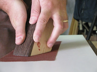


On the right side, in the same position, cut a groove with parallel bed. The two grooves will form the slot for the nicker and its wedge.
 The four plane parts (two central and two lateral) are coupled by screws: the left part sole will be flush with the central part, while the right one will be slightly higher (3 mm) so the main rebate will be created.

The two central pieces are distant enough for permitting to the cutting edge just to pass trough the mouth.


 Cut the slot for the moulding plane by sawing and chiselling it, then clean by a router plane.
A Forstner bit will help us to create the chip escapement. The bed is 5-6° inclined to right, so the shaves can escape more easily.


We are ready to level the sole. Do it with irons inserted in place, by 80 and 150 grit abrasive paper glued to a flat surface.

In order to positioning it to right level, where the moulding curve ends, I bored with two drill bits, 25 and 11 mm.
The posterior plane part is tapered and holds the cherry handle.


The following short video shows the plane in action.
What a satisfaction!
Read More..
Other than the main blade, it was equipped with an auxiliary iron for moulding the inner edge of the panel and a nicker for scoring the wood across the grain.
Woods are lamellar beech, wengè and cherry (handle). Here is the result:
The main blade (25° skew angle) has a chipbreaker and the "Stella Bianca" mark. It is a new old stock blade and showed very good quality and ability of keeping a sharp edge. The moulding iron comes from a file, shaped by bench grinder.
The first nicker (red point) comes from an old plane iron; it is inserted in a mortice and held in place by a wedge. Another nicker (green point) is present; it avoids the tearout of the moulding edge when the plane cuts across the grain.
The main wedge is kept in place by a 5 mm steel rod I obtained from a screwdriver.
A description of building the plane follows.
This is a Krenov-style plane, assembled in three parts, one central part where the main cutting group is held and two lateral parts.The central part will be large enough for the blade bedded in a skewed position. In this case it was obtained by gluing two pieces together (final width ca. 50 mm). The two lateral pieces are ca. 15 mm thick. The plane length is 13" (keep stock pieces some inches longer).
I glued a wengè sole (ca. 10 mm thick) to the three body pieces.
I glued a wengè sole (ca. 10 mm thick) to the three body pieces.
Then the left side has been screwed to the central part (temporarily) and a 6° angle (typical sole angle for these planes) cut by bench saw.
The left side is removed and a dozuki saw is used for cutting the bed and the facing part The bed angle is 50° (25° skew).
Try to cut as more precisely as possible; dont worry if the cut is approximative. The successive step of lapping the bed on abrasive paper (150 grit) will true it and dont matter if the final angle will be a couple of degrees more or less: more important is that the blade will seat firmly on its bed.
Cut the slot for cap iron screw and mould the right side sole by routering it (roman ogee profile).
The main nicker groove has a sloped bed, so its tip is aligned with the rebate inner wall.
On the right side, in the same position, cut a groove with parallel bed. The two grooves will form the slot for the nicker and its wedge.
The four plane parts (two central and two lateral) are coupled by screws: the left part sole will be flush with the central part, while the right one will be slightly higher (3 mm) so the main rebate will be created. The two central pieces are distant enough for permitting to the cutting edge just to pass trough the mouth.
Now we can insert the pin, (I needed a longer drill bit), paying attention the boring slope corresponds to seat.
Shape the wedge so it could firmly keep the iron in place.
Shape the wedge so it could firmly keep the iron in place.
A good wedge should can work simply inserted by hand.
The pin is cut a couple of mm shorter than necessary.
Now is the moment of gluing sides to two central pieces.
The pin is cut a couple of mm shorter than necessary.
Now is the moment of gluing sides to two central pieces.
A Forstner bit will help us to create the chip escapement. The bed is 5-6° inclined to right, so the shaves can escape more easily.
Glue up a 3 cm wide strip on the right side. It forms the moulding blade slot.
I decided to re-mouth the plane for inserting an end-grained piece before the mouth. It should offer a bigger resistance to wear.
I decided to re-mouth the plane for inserting an end-grained piece before the mouth. It should offer a bigger resistance to wear.
We are ready to level the sole. Do it with irons inserted in place, by 80 and 150 grit abrasive paper glued to a flat surface.
Sharp the blades so they could follow the wood profiles.
The second nicker cleans the inner edge of panel moulding. It comes from a Stanley 78 spare part (you can order here also).
In order to positioning it to right level, where the moulding curve ends, I bored with two drill bits, 25 and 11 mm.
The posterior plane part is tapered and holds the cherry handle.
A slide dovetail joint insures it to plane body. the male joint part has been cut by a dedicate plane.
The lateral fence and depth stop are screwed to body and have slotted holes for regulating field width and depth.
A strike button and a cherry insert (it covers the pin hole) on the left side complete the plane.
It received three coats of shellac and two coats of wax.The following short video shows the plane in action.
What a satisfaction!
Subscribe to:
Posts (Atom)